- Column/Beam Direct Weld Moment Connection
- Column/Beam Extended End Plate Moment Connection
- Column/Beam Flange Plate Moment Connection

Design for seismic moment connection detailing is done per the AISC Seismic Design Manual, 3rd Edition (2016) &2nd Edition (2010) contains two documents: the AISC 341-16/10 Seismic Provisions for Structural Steel Buildings and the AISC 358-16/10 Prequalified Connections for Special and Intermediate Steel Moment Frames for Seismic Applications. These documents contain common design standards for seismic systems, including seismic connection design criteria.
The following seismic moment connections are available:
Note:
If you are using RISAConnection as a stand-alone program, then you can define your seismic moment connection as follows:

If you are using the integration between RISA-3D and RISAConnection to create your model, then you can define your seismic connection as follows:
RISA-3D:
RISAFloor:
Determining the Seismic System
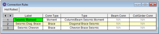
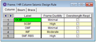
The integration between programs uses the following "translation" to determine the Seismic System for moment connections:
![]()
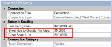
The following seismic input values are available for moment connections:
Below is a list of limitations regarding the seismic design:
A Reduced Beam Section moment connection may be defined in RISAConnection as the "RBS" Seismic System within the Column/Beam Direct Weld Moment Connection. Depending on the ductility of your system, you may assign the RBS as an OMF, IMF, or SMF. The design of this type of connection is done per AISC 341-16 and AISC 358-16, chapter 5. Please see the Seismic Moment Connection Checks section for more information.
When you use this connection type, the following changes to geometry and assembly apply:
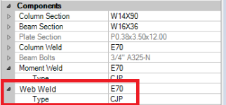
In addition to the existing welding/bolting requirements of the moment connections, the Column/Beam Direct Weld Moment Connection includes the "Web Weld". This weld is between the beam web and the column flange. It is required per AISC 358-16 chapter 5, section 5.6 (2) (a) (for RBS) and per AISC 358-16 chapter 7, section 8.6 (5) (for WUF-W). This weld must be a CJP with an electrode type of either E70 , E80, or E90.
RISAConnection will automatically modify the geometry of the RBS and WUF-W seismic connections to include the Weld Access Hole Requirements of the AISC 358-16. This manual refers to the AWS D1.8/D1.8M 2009 section 6.10.1.2. RISAConnection uses the limits of this code to determine the geometry of the Weld Access Holes:

Note:
RISAConnection will apply default dimensions to the reduced beam section. But you may edit these at any time in the Assembly section of the Connection Properties.

RISA-3D Integrated Models
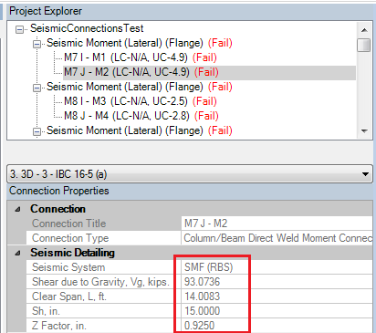
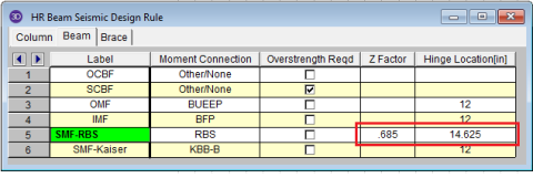
When a seismic moment RBS connection is imported from RISA-3D, the a, b, and c dimensions are predetermined from the RISA-3D Seismic Design Rules data. In the RISA-3D Seismic Design rule, you are required to input a Z Factor (ratio of reduced section Z to full section Z) and a Hinge Location ( distance from face of column flange to the center of the reduced section.
Seismic Design Rule spreadsheet from RISA-3D:
In order to assure that the RISA-3D results are consistent with the RISAConnection results, RISAConnection will then automatically calculate these dimensions.

A Welded Unreinforced Flange- Welded Web moment connection may be defined in RISAConnection as the "WUF-W" Seismic System within the Column/Beam Direct Weld Moment Connection. Depending on the ductility of your system, you may assign the WUF-W as an OMF, IMF, or SMF. The design of this type of connection is done per AISC 341-16 and AISC 358-16, chapter 8. Please see the Seismic Moment Connection Checks section for more information.
When you use this connection type, the following changes to geometry and assembly apply:
Web Weld Entry
In addition to the existing welding/bolting requirements of the moment connections, the Column/Beam Direct Weld Moment Connection includes the "Web Weld". See the discussion above for more information.
Weld Access Holes
RISAConnection will automatically modify the geometry of the RBS and WUF-W seismic connections to include the Weld Access Hole Requirements of the AISC 358-16. See the discussion above for more information.
WUF-W Dimensions
RISAConnection will apply default dimensions to the WUF-W shear plate. But you may edit these at any time in the Assembly section of the Connection Properties.

WUF-W Limitations
A Bolted Unstiffened or Stiffened Extended End-Plate moment connection may be defined in RISAConnection as the "BEEP" Seismic System within the Column/Beam Extended End Plate Moment Connection. The end plate can be stiffened of unstiffened depending on if you have applied a stiffener plate in the Connection Category input of Connection Properties (this is required for 8 bolt layouts).
Depending on the ductility of your system, you may assign the BEEP as an OMF, IMF, or SMF.
The design of this type of connection is done per AISC 341-16 and AISC 358-16, chapter 6. Please see the Seismic Moment Connection Checks section for more information.
A Bolted Flange Plate moment connection may be defined in RISAConnection as the "BFP" Seismic System within the Column/Beam Flange Plate Moment Connection. Depending on the ductility of your system, you may assign the BFP as an OMF, IMF, or SMF.
The design of this type of connection is done per AISC 341-16 and AISC 358-16, chapter 7. Please see the Seismic Moment Connection Checks section for more information.
The AISC 358-16 is specifically for the design of seismic IMF & SMF connections. However, you are allowed to define your connection as an Ordinary Moment Frame (OMF) using any of the AISC 358-16 pre-qualified connection types. In this case, many of the checks will be for reference only as they are not specifically required by the design code.
Per AISC 341-16 section E1.6b, the flexural strength of an OMF shall be the lesser of:
Per AISC 341-16 section E1.6b, the required shear strength of an OMF is computed using the AISC 360-16 (15th edition) load combinations.
When a model is imported from RISA-3D, these values are brought over from the RISA-3D seismic detailing calculations. When a model is created using the stand-alone version of RISAConnection, the user is expected to enter these values.
The following checks are included with the regular (AISC 360-16, 15th edition) checks for seismic moment connections. The seismic checks will always be shown at the bottom of the results report fpr seismic moment connections.
If you are using a RISA-3D integrated model, these checks do not depend on the loads from the load combinations. The seismic checks design to a probable maximum moment which is independent of the actual applied forces.
Seismic Material and Geometry Limitations -
This check includes material geometry limits from the AISC 341-16 and from the applicable chapter in the AISC 358-16. Specific code section references are presented in the output report.
Seismic Width to Thickness Ratios-
This check includes width to thickness ratio checks per AISC 341-16, Table D1.1.
For OMF connections, this check is for reference only.
Seismic Moment at Face of Column-
This section calculates the probable maximum moment at the face of the column, Mf and the design flange force, F. This is required by all connection types per the AISC 358-16. Specific code section references are presented in the output report.
For OMF connections, this check is for reference only. RISAConnection will check to see which is the minimum design moment (R*Mu or Mpr) and which is the minimum design shear (R*Vu or Vh) and then use that to calculate the design flange force. Based on the AISC 341-16 commentary, the required moment of minimally ductile moment frames need not exceed R*Mu.
Seismic Parametric Limitations-
This check is only applicable to Extended End Plate Moment Connections (BSEEP, BUEEP). It includes geometry limitation checks based on AISC 358-16, Table 6.1.
This checks the requirements of AISC 341-16, section A4 and the specific weld requirements of each chapter in the AISC 358-16. Specific code section references are presented in the output report.
Seismic Flange Bolt Limitations-
This check is only applicable to Bolted Flange Plate Moment Connections (BFP). It checks the bolt size and spacing requirements of AISC 358-16 chapter 7. Specific code section references are presented in the output report.
Seismic Flange Plate Limitations-
This check is only applicable to Bolted Flange Plate Moment Connections (BFP). It checks the beam flange plate thickness and connection limitations of AISC 358-16 chapter 7. Specific code section references are presented in the output report.
This check is only applicable to Extended End Plate Moment Connections (BSEEP, BUEEP). It checks the bolt material and size requirements of AISC 358-16 chapter 6. Specific code section references are presented in the output report.
Seismic Plate / Misc Limitations-
This check is only applicable to Extended End Plate Moment Connections (BSEEP, BUEEP). This checks the end plate width limitation as well as the end plate and the column flange for "thick" plate behavior. The "thick plate" check is covered in the AISC Design Guide #4 "Extended End-Plate Moment Connections", 2nd edition, Section 3.3. This is the same as the regular Verify Bolt Prying Assumption check.
Seismic End Plate Limitations-
This check is only applicable to Extended End Plate Moment Connections (BSEEP, BUEEP). It checks the end plate thickness and width requirements of AISC 358-16 chapter 6. Specific code section references are presented in the output report.
Seismic RBS Connection Detail Limitations-
This check is only applicable to Direct Weld - Reduced Beam Section Moment Connections (RBS). It checks the reduced beam section geometry requirements of AISC 358-16 chapter 5. Specific code section references are presented in the output report.
Seismic WUF-W Connection Detail Limitations-
This check is only applicable to Direct Weld - Welded Unreinforced Flange-Welded Web Moment Connections (WUF-W). It checks the WUF-W shear plate geometry requirements of AISC 358-16 chapter 8. Specific code section references are presented in the output report.
Seismic Column-Beam Moment Ratio-
This section calculates the column-beam moment ratio. This is required for all SMF connection types per AISC 341-16, section E3.4a. Specific code section references are presented in the output report. Because RISAConnection only has column and loading information for the one column, only a single story height column will be considered in the calculation of M*pc (projected flexural strength of the column).
For OMF and IMF connections, this check is for reference only.
Seismic Flexural Strength of Beam-
This check is only applicable to Direct Weld - Reduced Beam Section Moment Connections (RBS). It checks the flexural strength of the beam at the face of the column per AISC 358-16, equation (5.8-8).
This check is only applicable to Bolted Flange Plate Moment Connections (BFP). It checks the beam flange tensile rupture, block shear, and compression buckling per AISC 358-16 section 7.6. Specific code section references are presented in the output report.
This checks the beam web shear limit states per AISC 358-16. Specific code section references are presented in the output report.
This check is only applicable to Extended End Plate Moment Connections (BSEEP, BUEEP). It checks the end plate shear limit states of AISC 358-16 chapter 6. Specific code section references are presented in the output report.
Seismic End Plate Flexural Yielding-
This check is only applicable to Extended End Plate Moment Connections (BSEEP, BUEEP). It checks the end plate design strength per AISC 358-16, equation (6.8-5) (AISC 358-10, equation (6.10-5)).
This check is only applicable to Extended End Plate Moment Connections (BSEEP, BUEEP). It checks the bolt shear and bearing limit states of AISC 358-16 chapter 6. Specific code section references are presented in the output report.
This check is only applicable to Extended End Plate Moment Connections (BSEEP, BUEEP). It checks the bolt moment strength against the probable seismic design flange force per AISC 358-16, equation (6.8-3) (AISC 358-10, equation (6.10-3)).
Seismic Flange Bolt Shear Strength-
This check is only applicable to Bolted Flange Plate Moment Connections (BFP). It checks the flange bolt shear strength per AISC 358-16, equation (7.6-8).
This check is only applicable to Bolted Flange Plate Moment Connections (BFP). It checks the beam web bolt bearing and shear limit states per AISC 358-16, chapter 7. Specific code section references are presented in the output report.
This check is only applicable to Bolted Flange Plate Moment Connections (BFP). It checks the beam web shear plate (vertical plate) shear limit states per AISC 358-16, chapter 7. Specific code section references are presented in the output report.
This check is only applicable to Direct Weld - Welded Unreinforced Flange-Welded Web Moment Connections (WUF-W).It checks the column weld shear strength per AISC 358-16, section 8.6 (2).
This check is only applicable to ordinary moment frames (OMF). It checks the column limit states per AISC 341-16, section E1.6b.
This check is only applicable to Extended End Plate Moment Connections (BSEEP, BUEEP). It checks the column web limit states per AISC 341-16 section E1.6b.
Seismic Column Flexural Yielding-
This check is only applicable to Extended End Plate Moment Connections (BSEEP, BUEEP). It checks the column flange design strength per AISC 358-16, equations (6.8-14 & 6.8-15) (AISC 358-10, equations (6.10-14 & 6.10-15)).
Seismic Stiffener Plate Limitations-
This checks the transverse stiffeners (continuity plate) requirements per AISC 341-16, section E3.6f (2). If this check fails, then continuity plates are required.
This check is only applicable to Extended End Plate Moment Connections (BSEEP, BUEEP). It is only included when transverse stiffeners (continuity plates) are included in the model. This will check the transverse stiffener strength per AISC 358-16, section 6.8.2 step 6 (AISC 358-10, section 6.10.2 step 6). Specific code section references are presented in the output report.
Seismic Panel Zone Limitations-
This check only applies to special moment frames (SMF). It checks the panel zone thickness requirements per AISC 341-16, section E3.6e (2). If this check fails, then web doubler plates are required.
This checks the shear strength of the panel zone per the requirements of the AISC 358-16. Specific code section references are presented in the output report. If this check fails, then web doubler plates are required.
For OMF connections, this check is per the regular AISC 360-16 (15th edition) section J10.6.
For OMF and IMF connections, this check is for reference only.
Seismic Doubler Plate Strength-
This checks the yield strength and weld strength of the doubler plate against the required doubler plate shear force due to seismic forces. Specific code section references are presented in the output report.
Because Seismic Panel Zone shear is only applicable to SMF connections, this check is not applicable to OMF or IMF connections.
In addition to the regular DXF output, the seismic moment connections will include: